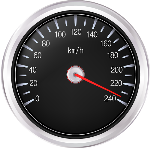
This image has format transparent PNG with resolution 503x496.
You can download this image in best resolution from this page and use it for design and web design.
Speedometer PNG with transparent background you can download for free, just click on download button.
A speedometer or a speed meter is a gauge that measures and displays the instantaneous speed of a vehicle. Now universally fitted to motor vehicles, they started to be available as options in the 1900s, and as standard equipment from about 1910 onwards.[1] Speedometers for other vehicles have specific names and use other means of sensing speed. For a boat, this is a pit log. For an aircraft, this is an airspeed indicator.
Charles Babbage is credited with creating an early type of a speedometer, which were usually fitted to locomotives.
The electric speedometer was invented by the Croatian Josip Belu?i? in 1888, and was originally called a velocimeter.
Originally patented by Otto Schultze on October 7, 1902,[5] it uses a rotating flexible cable usually driven by gearing linked to the output of the vehicle's transmission. The early Volkswagen Beetle and many motorcycles, however, use a cable driven from a front wheel.
When the car or motorcycle is in motion, a speedometer gear assembly turns a speedometer cable, which then turns the speedometer mechanism itself. A small permanent magnet affixed to the speedometer cable interacts with a small aluminum cup (called a speedcup) attached to the shaft of the pointer on the analogue speedometer instrument. As the magnet rotates near the cup, the changing magnetic field produces eddy currents in the cup, which themselves produce another magnetic field. The effect is that the magnet exerts a torque on the cup, "dragging" it, and thus the speedometer pointer, in the direction of its rotation with no mechanical connection between them.
The pointer shaft is held toward zero by a fine torsion spring. The torque on the cup increases with the speed of rotation of the magnet. Thus an increase in the speed of the car will twist the cup and speedometer pointer against the spring. The cup and pointer will turn until the torque of the eddy currents on the cup is balanced by the opposing torque of the spring, and then stop. Given the torque on the cup is proportional to the car's speed, and the spring's deflection is proportional to the torque, the angle of the pointer is also proportional to the speed, so that equally spaced markers on the dial can be used for gaps in speed. At a given speed the pointer will remain motionless and pointing to the appropriate number on the speedometer's dial.
The return spring is calibrated such that a given revolution speed of the cable corresponds to a specific speed indication on the speedometer. This calibration must take into account several factors, including ratios of the tailshaft gears that drive the flexible cable, the final drive ratio in the differential, and the diameter of the driven tires.
One of the key disadvantages of the eddy current speedometer is that it cannot show the vehicle speed when running in reverse gear since the cup would turn in the opposite direction - in this scenario the needle would be driven against its mechanical stop pin on the zero position.
In this clipart you can download free PNG images: Speedometer PNG images free download